
Introduction
The information on this web site is supplemental to the printed instructions that came with your water heater. To reduce the risk of property damage, serious injury or death, read and follow all labels on the water heater and the safety instructions in the printed owner's manual.
Tools
-
-
Box cutter
-
Hand dishwashing soap or children's soap bubbles
-
Hand truck or appliance dolly
-
Soft bristled brush
-
Marker
-
Plumber's tape or pipe joint compound approved for potable water and plumber's tape or pipe joint compound approved for fuel gas.
-
Pipe cutter
-
Nut driver, power drill, and wrenches
-
-
-
Drain pan
-
For homes with copper pipes, consider purchasing an Gas Water Heater Installation Kit (available from hardware stores and home centers) with compression fittings that don’t require soldering.
-
Thermostatic mixing valves
-
-
-
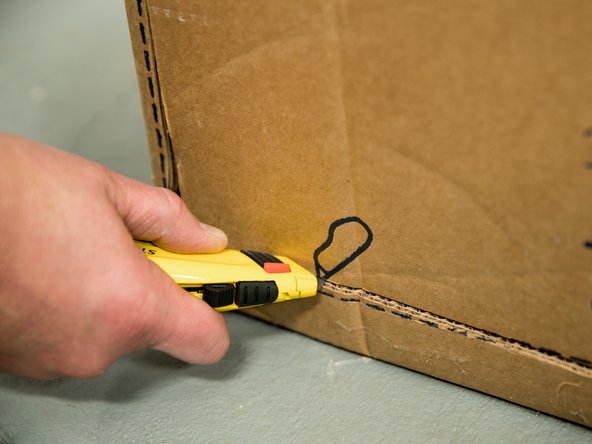
Cut the water heater box along the dotted lines.
-
-
-
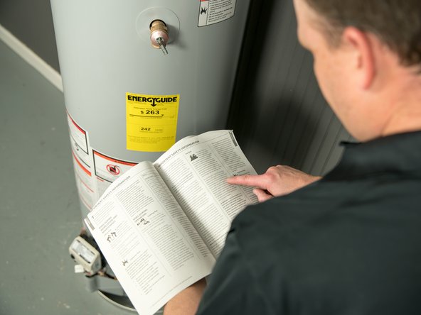
Read the printed installation instructions, including all of the safety warnings, before beginning.
-
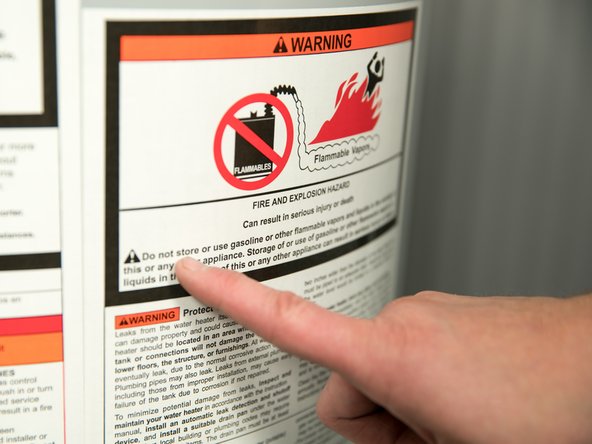
Read all of the labels on the water heater.
-
It is your responsibility to ensure that the installation complies with national, state and local building, plumbing and electrical codes.
-
NOTICE: If you are not sure you can correctly and safely complete the installation, seek assistance from a qualified professional.
-
-
-
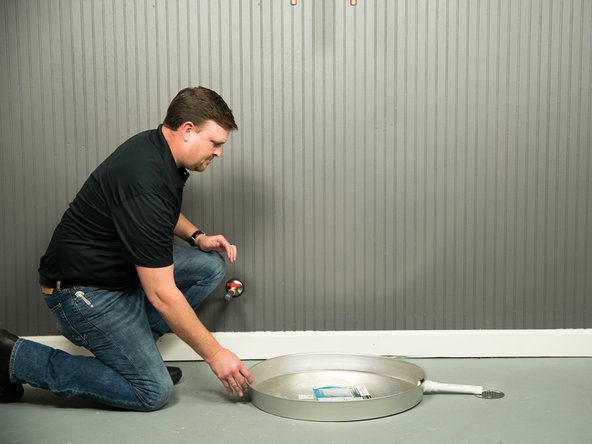
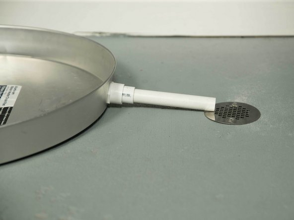
Install a metal drain pan that is piped to an adequate drain. Install the drain pan so the water level is limited to a maximum depth of 1-3/4".
-
The drain pan must be at least two inches wider than the diameter of the water heater.
-
-
-
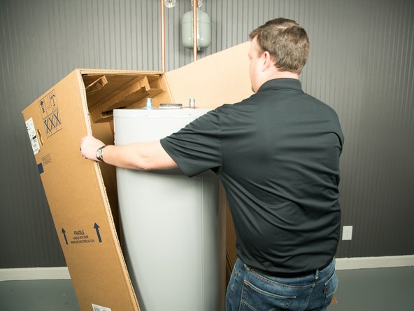
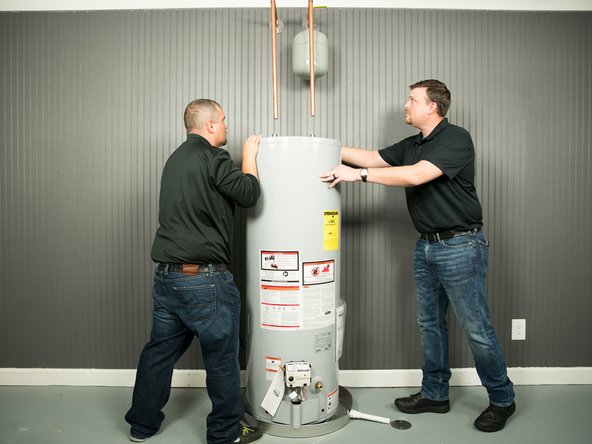
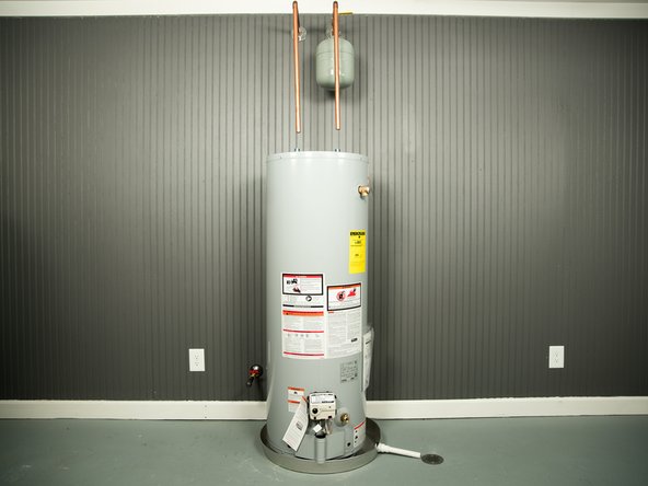
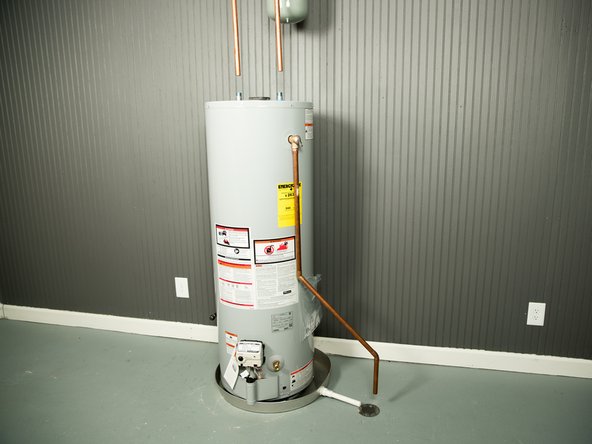
Install the water heater in the drain pan. Set the water heater in place, taking care not to damage the drain pan.
-
CAUTION: Water heaters are heavy. Use two or more people to remove or install a water heater if you don't have an appliance dolly. Failure to do so can result in back or other injury.
-
Verify there is adequate access and space around the water heater for future maintenance.
-
-
-
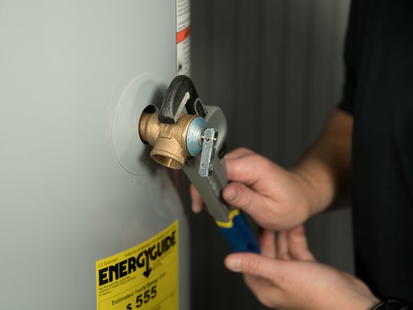
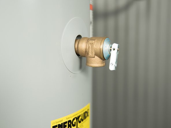
Most Temperature and Pressure (T&P) Relief Valves are installed at the factory. If your T&P Relief Valve is in a separate carton, it must be installed in the opening marked "T&P Relief Valve." Use the new T&P Relief Valve supplied with your new water heater. Do not reuse the old one.
-
WARNING! To avoid serious injury or death from explosion, install the T&P Relief Valve (if your water heater does not have a factory installed one) and the discharge pipe according to the printed installation instructions.
-
-
-
Install the discharge pipe. The discharge pipe should be at least 3/4” inside diameter and sloped for proper drainage. Install it to allow complete drainage.
-
The discharge pipe must withstand 250°F (121°C) without distortion. Use only copper, PEX, or CPVC pipe. Do not use any other type of pipe, such as PVC, iron, flexible plastic pipe, or any type of hose.
-
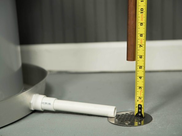
Terminate the discharge pipe at least 1" and a maximum of 6" above a floor drain or outside. Do not drain the discharge pipe into the drain pan; instead, pipe it to an adequate drain.
-
In cold climates, terminate the discharge pipe inside the building to an adequate drain. Outside drains could freeze and obstruct the drain line.
-
WARNING! Do not place any valve or other restriction between the tank and T&P Relief Valve. Do not cap, block, plug, or insert any valve between the T&P Relief Valve and the end of the discharge pipe. Do not insert or install any reducer in the discharge pipe.
-
-
-
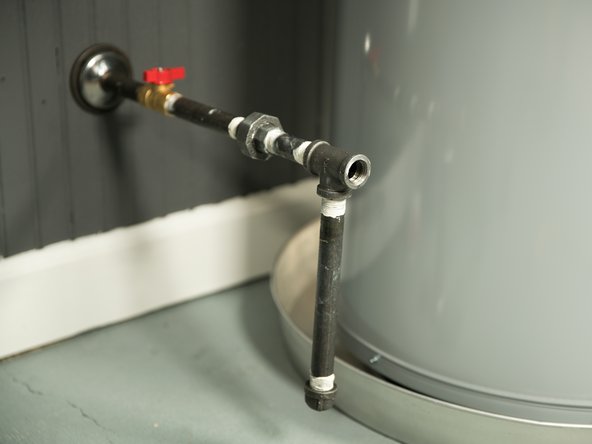
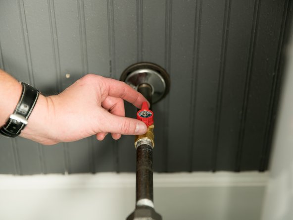
If one is not already installed, install a manual shutoff valve in the cold water line that supplies the water heater. Install the shutoff valve near the water heater so that it is readily accessible. Only use a full-flow ball or gate valve compatible with potable water.
-
This step varies depending on your water heater's location and piping. Consult the installation instructions.
-
-
-
Install a Thermostatic Mixing Valve at each point of use (for example, kitchen sink, bathroom sink, bath, shower) per the valve manufacturer’s instructions.
-
For water heaters that are fed by a solar water heating system (or any other pre-heating system), always install a Thermostatic Mixing Valve or other temperature limiting device in the inlet water supply line to limit water supply inlet temperature to 120°F.
-
WARNING! Hot water can cause severe burns instantly, resulting in severe injury or death. Install Thermostatic Mixing Valves at each point of use to reduce the risk of scalding.
-
-
-
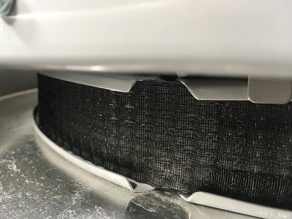
Once you’ve positioned the water heater in the installation area, install the wrap-around air filter (supplied with the water heater) if not already installed. The wrap-around air filter fits around the base of the unit. Do not operate the water heater without a clean air filter in place.
-
Connect the end points of the filter sections together to form one long section. Wrap this section around the base of the water heater and join at the closest connection point to fit your water heater. If your water heater has a small diameter tank, it may be necessary to use both inner connection points.
-
The air filter will require periodic cleaning to keep the water heater working properly. See Maintenance section for advice on cleaning the air filter.
-
-
-
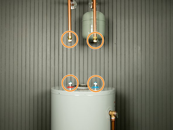
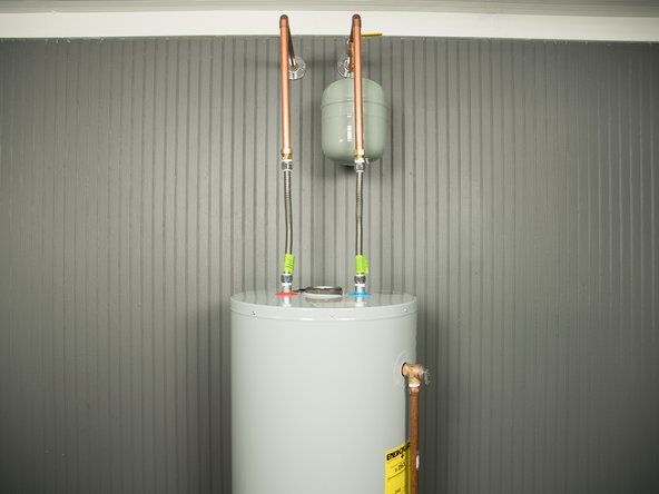
For ease of removing the water heater for service or replacement, use compression fittings to connect the water pipes. If you are soldering copper pipes, use dielectric unions to connect the pipes to the water heater.
-
Installation kits are available with flexible stainless steel connectors and compression fittings that don't require soldering. And many flexible connectors contain built-in dielectric fittings. Use fittings appropriate for the type of pipe in your home. Use copper, PEX or CPVC pipe. Do not use iron or PVC pipe.
-
NOTICE: Do not solder pipes while they are attached to the water heater. The water heater’s inlet and outlet connections contain non-metallic parts which could be damaged.
-
-
-
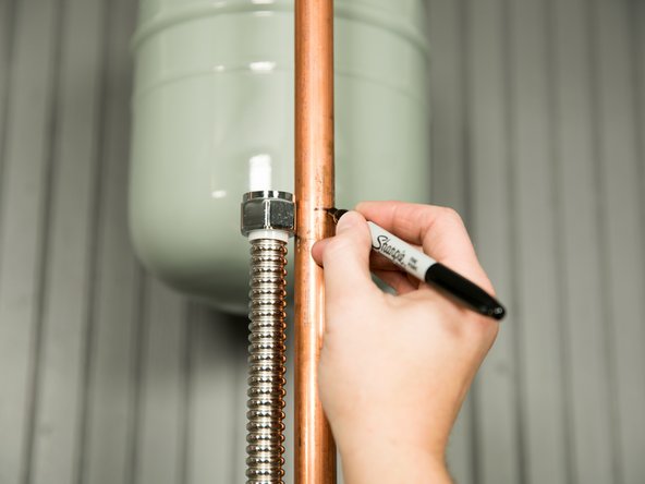
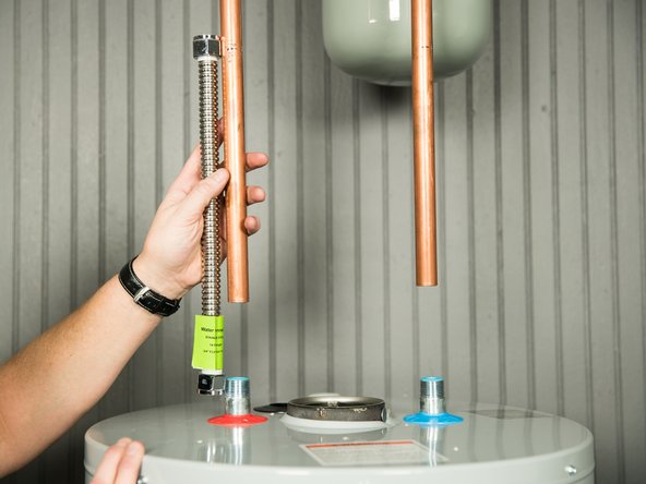
If you are using the installation kit, measure both of the water lines.
-
-
-
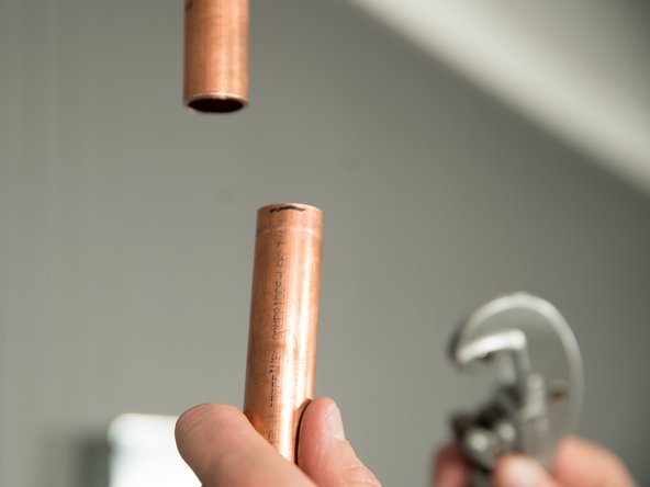
Cut both of the water pipes, but leave them a little longer than the measurement. You can always cut them shorter if necessary.
-
-
-
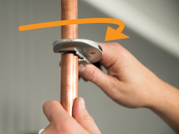
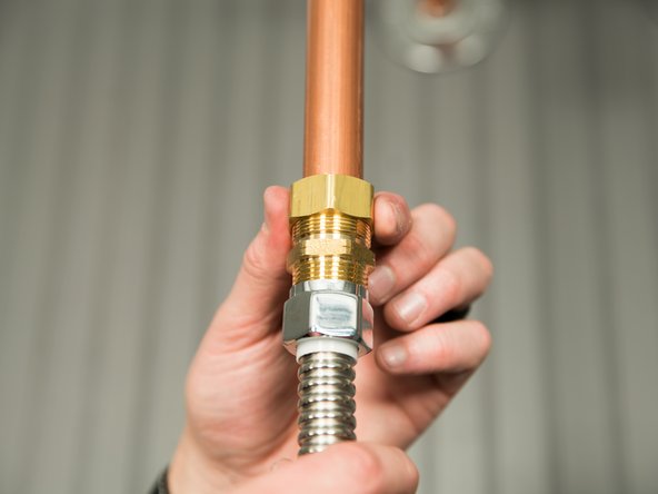
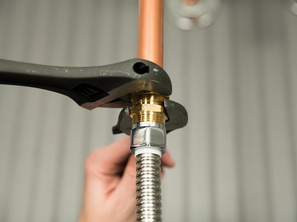
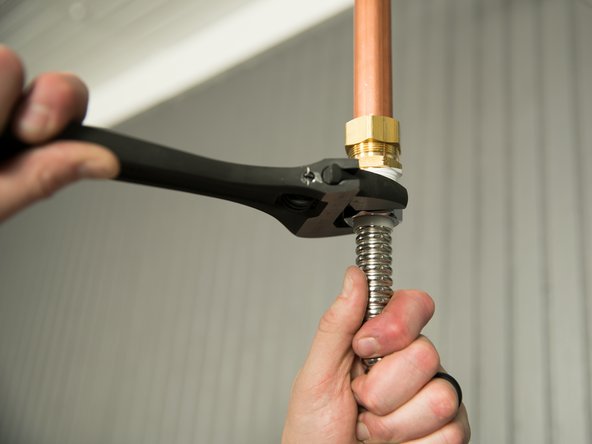
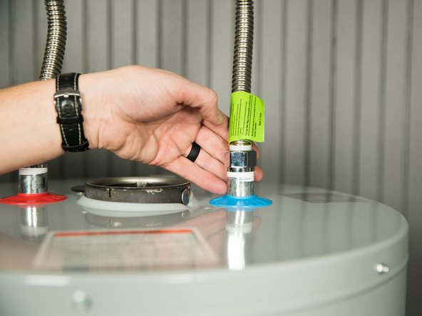
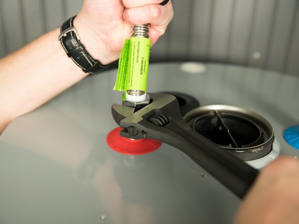
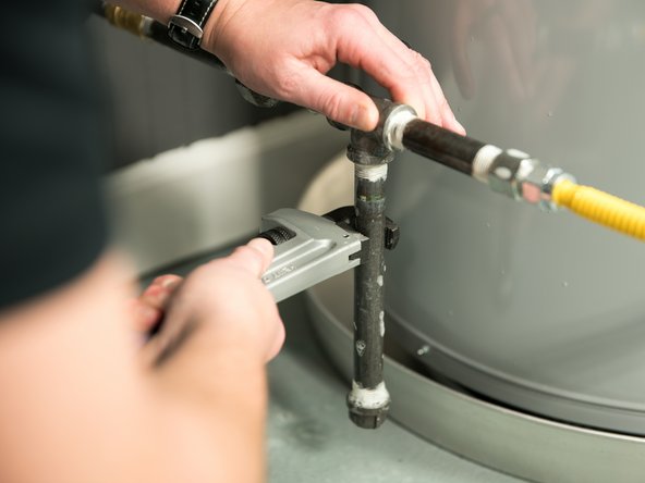
Install compression fittings on both water lines and tighten.
-
Temporarily use the flex connector as a brace for ease of installation.
-
-
-
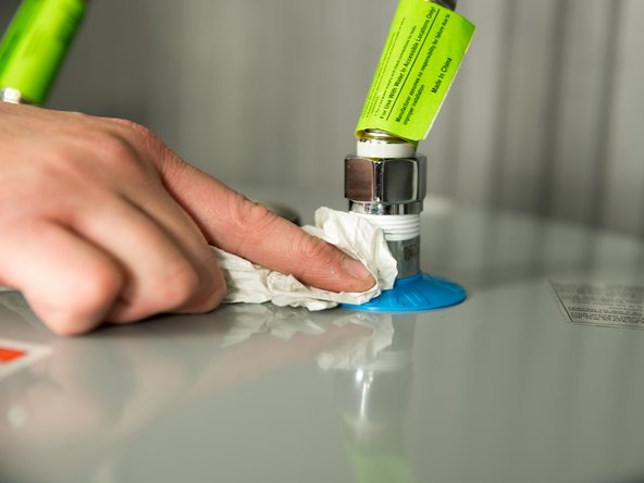
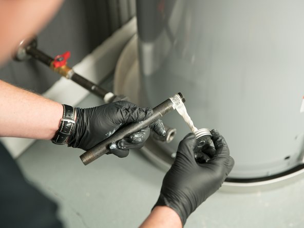
Use pipe joint compound or plumber's tape on the threaded connections only.
-
-
-
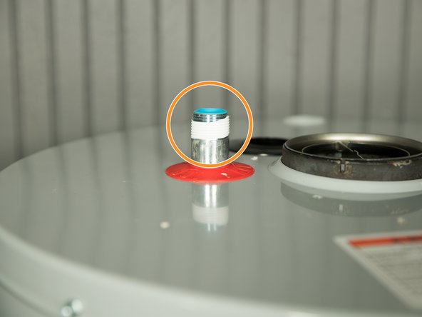
Connect the cold water supply using a 3/4" NPT threaded adapter to the outlet connection on the water heater marked “C” (COLD).
-
Connect the hot water supply using a 3/4" NPT threaded adapter to the outlet connection on the water heater marked “H” (HOT).
-
-
-
Make sure the home's hot and cold water pipes are connected to the correct hot and cold water fittings on the water heater.
-
-
-
Dry the pipe connections so that any drips or leaks will be apparent.
-
-
-
Turn the cold water supply back ON and fill the tank.
-
-
-
To remove air from the tank and allow the tank to fill completely with water, follow these steps:
-
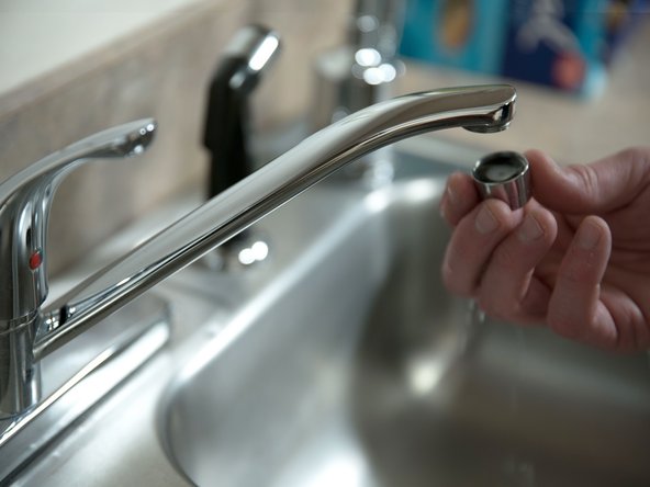
Remove the aerator at the nearest hot water faucet. This allows any debris in plumbing system to be washed out of the pipes.
-
-
-
Open a hot water faucet and allow the water to run until it flows full stream.
-
Let the water run full stream for THREE MINUTES to get all of the air out of the tank.
-
-
-
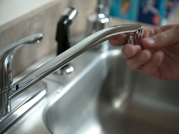
After all of the air has been removed from the tank, close the hot water faucet and replace the aerator.
-
-
-
Check inlet and outlet connections and water pipes for leaks. Tighten fittings or repair any leaks.
-
Almost all leaks occur at connections and are not a tank leak.
-
-
-
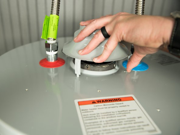
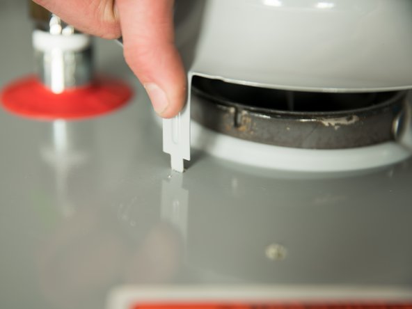
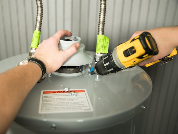
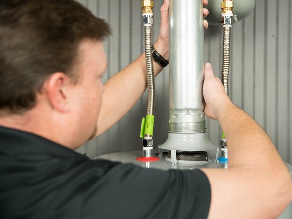
Install the new draft hood by inserting the legs into the slots on top of the water heater.
-
Do not reuse the draft hood from the old water heater. Use the new draft hood that came with your new water heater.
-
-
-
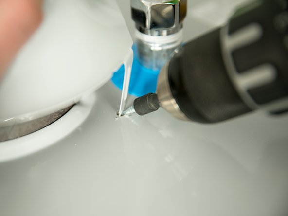
Secure the draft hood using the four screws provided.
-
-
-
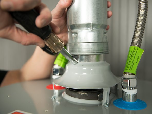
Attach the home’s existing vent pipe to the draft hood outlet using an approved vent adapter.
-
Secure the vent pipe to the draft hood with sheet metal screws.
-
Make sure your home’s venting system complies with the printed instruction manual and is in good condition.
-
-
-
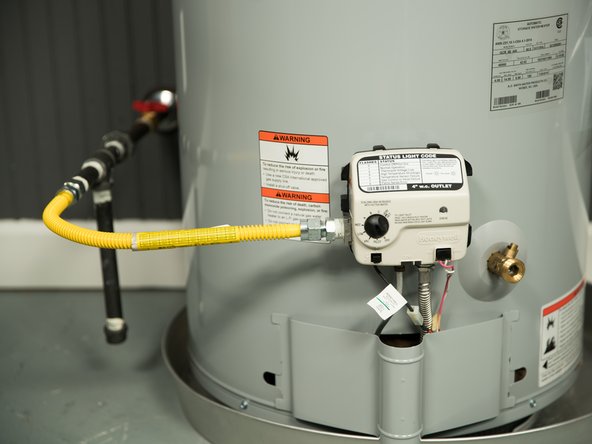
The installation kit includes a flexible gas connector with compression fittings to connect the home’s gas pipe to the water heater’s gas control valve. Follow the kit’s installation instructions to attach the flexible gas connector.
-
Threaded iron or steel pipe connectors require pipe joint compound or plumber's tape approved for fuel gas. When using pipe joint compound, be sure to leave the last two threads clean.
-
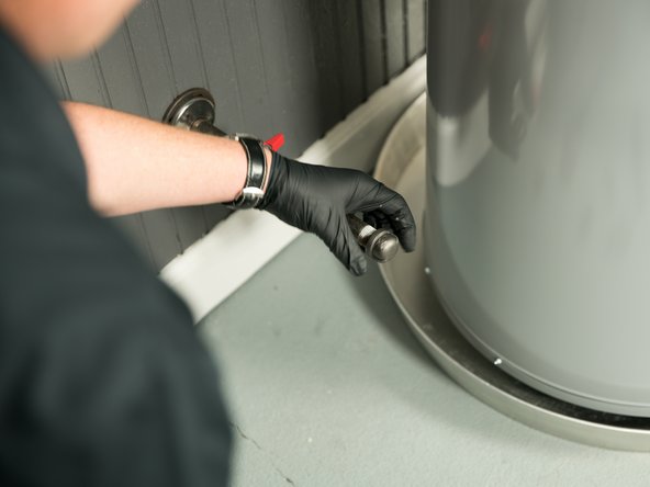
Remove cap from gas pipe.
-
-
-
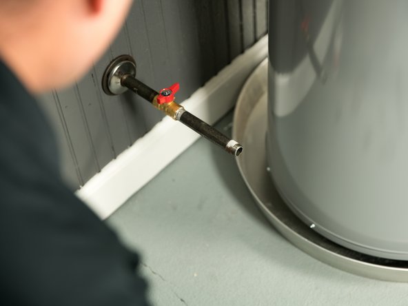
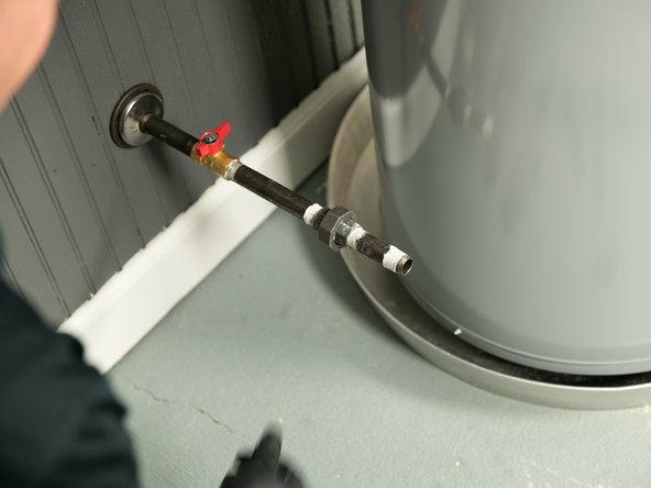
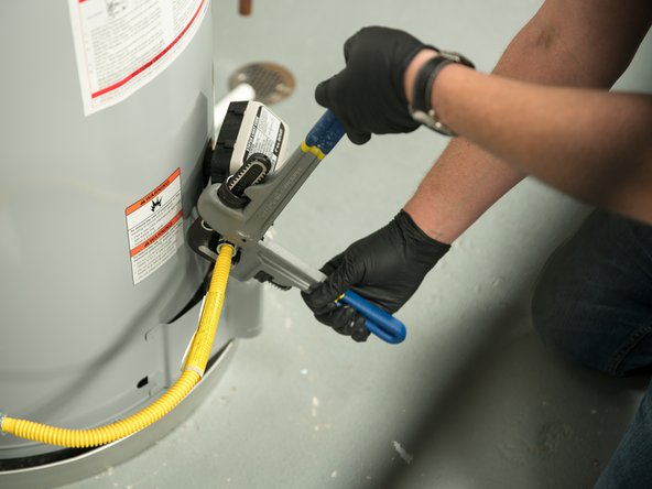
Install the union.
-
-
-
Install the drip leg.
-
-
-
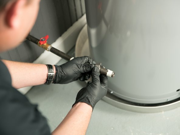
Install the flexible gas line connector.
-
-
-
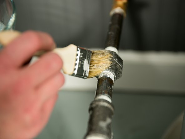
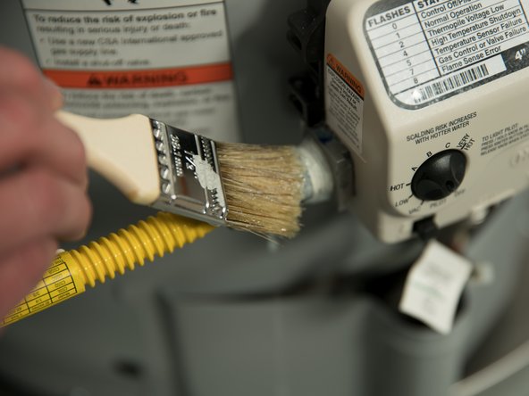
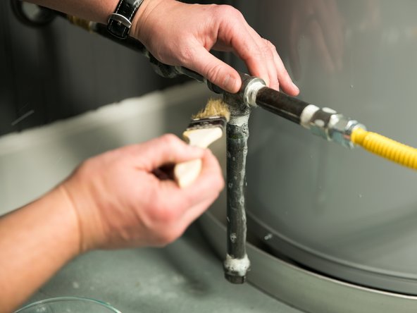
Once you’ve made the gas connections, use a soft-bristled brush to apply a mixture of hand dish washing soap and water or children’s soap bubbles to all gas pipe connections and the flexible gas connector (if used).
-
To make soap bubble solution, use 1 part hand dishwashing soap and 15 parts water.
-
-
-
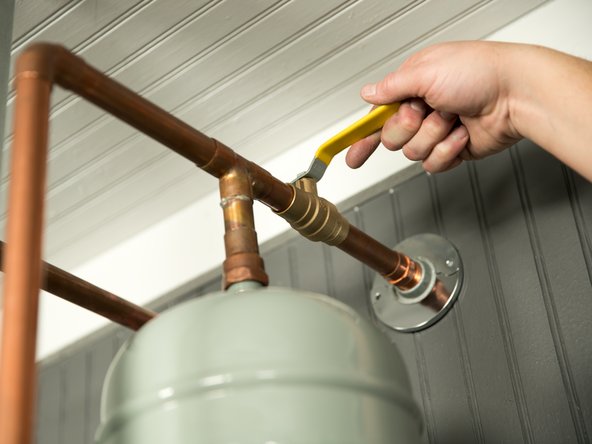
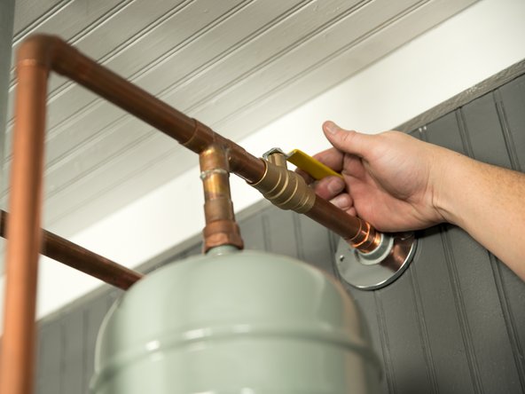
Turn the gas supply valve ON.
-
-
-
Look carefully for any leaks (which will appear as small bubbles).
-
Continue to apply liberal amounts of soap bubble solution.
-
If any leaks are detected, turn the gas supply off, tighten the leaking connection and re-check.
-
-
-
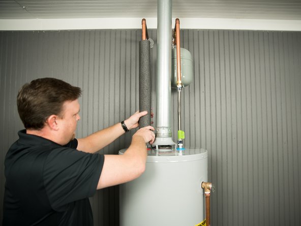
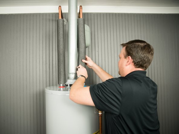
Install insulation (or heat tape) on the water pipes, especially if the indoor installation area is subject to freezing temperatures.
-
Insulating the hot water pipe can increase energy efficiency.
-
-
-
Make sure the gas supply is ON.
-
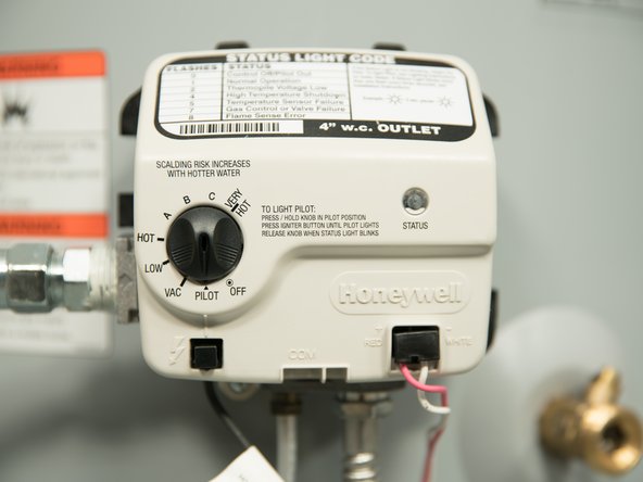
Light the water heater using the instructions on the water heater's label.
-
Because the water heater is new, there will be air in the gas pipe. It may take several attempts to light the pilot.
-
-
-
When the pilot is lit, the status light will begin to blink.
-
-
-
Since the water heater is new and the tank is cold, you may get some condensation (water droplets) on the floor the first time the water heater operates. This is normal. Condensation may also occur in very cold weather or during periods of heavy use.
-
-
-
WARNING! Hot water can cause severe burns instantly, resulting in severe injury or death. Install Thermostatic Mixing Valves at each point-of-use to reduce the risk of scalding.
-
Read and follow the scald warning information on the water heater and in the owner's manual.
-
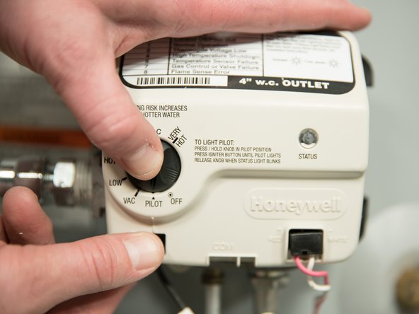
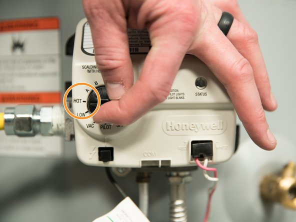
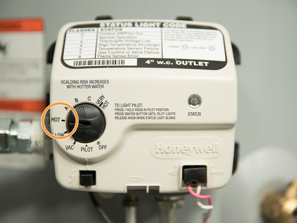
Set the thermostat on the water heater to "HOT" which is approximately 120°F degrees.
-
You can set the thermostat temperature higher than 120°F if you install thermostatic mixing valves at each point of use and set them to 120°F or lower.
-
-
-
Check water temperature at several points of use in your home (for example, bathtub faucet, shower, or lavatory sink) and adjust the Thermostatic Mixing Valves as needed.
-


Team

3 Comments
Step 8
Pic 1 inserting draft hood legs (must be able to see entire draft hood)
Pic 2 insert screws to hold legs
Pic 3 attaching vent pipe with screws to draft hood
Step 9
Pic 1 table top unbranded generic hand dishwashing liquid and water with brush and bottle of children’s soap bubbles.
Pic 2 turning main gas supply valve on
Pic 3 brushing on bubble solution.
Step 10
Pic 1 pic of lighting instruction label from water heater
Pic 2 pic of check list from I&O
Pic 3 cu status light flashing
Step 11
Pic 1 picture of scald warning label
Pic 2 installed mixing valve
Pic 3 pic of fingers setting control knob to HOT
Henry James - Resolved on Release Reply
Getting Started (edit)
Removing the old water heater
Standard gas electronic installation
Standard gas electronic troubleshooting
Standard gas mechanical installation
Standard gas mechanical troubleshooting
Electric prerequisites
Standard electric installation
Standard electric troubleshooting
Energy Saver (Energy Smart) installation
Energy Saver (Energy Smart) troubleshooting
EE troubleshooting (lite)
Step 5
Pic 1 full flow (ball valve) shut off valve installed on cold water side
Pic 2 scald graphic water heater label.
Pic 3 tabletop shot of thermostatic mixing valve
Step 6
Pic 1 table top installation kit. Call out compression fittings/stainless steel connectors
Pic 2 table top cu of above photo calling out dielectric union
Pic 3 table top cu of dielectric union for copper pipe
Step 7
Pic 1 Turning cold water supply valve on
Pic 2 Open a hot water faucet with water running full stream
Pic 3 Checking for leaks around a pipe connection with paper towel (see me)
Henry James - Resolved on Release Reply
Getting Started (edit)
Removing the old water heater
Standard gas electronic installation
Standard gas electronic troubleshooting
Standard gas mechanical installation
Standard gas mechanical troubleshooting
Electric prerequisites
Standard electric installation
Standard electric troubleshooting
Energy Saver (Energy Smart) installation
Energy Saver (Energy Smart) troubleshooting
EE troubleshooting (lite)
Step 1
Graphic installation video
Step 2
Pic 1 two people installing new water heater using two wheeler
Pic 2 table top shot of metal drain pan
Pic 3 graphic of water heater in tight space with arrows indicating need for some space (not specific) for maintenance.
Step 3
Graphic wrapping and cleaning air filter gif (follow text)
Step 4
Pic 1 table top shot of T&P
Pic 2 T&P valve with copper discharge pipe attached (wide shot with call out)
Pic 3 discharge pipe termination with 1” and 6” call out. Show dog leg and drain.
(These pictures must be precisely correct—see I&O)
Henry James - Resolved on Release Reply