
Introduction
The information on this web site is supplemental to the printed instructions that came with your water heater. To reduce the risk of property damage, serious injury or death, read and follow all labels on the water heater and the safety instructions in the printed owner's manual.
-
-
Box cutter
-
Marker
-
Thermometer
-
Non-contact circuit tester
-
Paper towels or shop rags
-
Pipe cutter
-
Pipe joint compound or plumber's tape
-
1/4" nut driver and/or Phillip's screwdriver and wrench
-
-
-
Drain pan
-
For homes with copper pipes, consider purchasing an Electric Water Heater Installation Kit (available from hardware stores and home centers) which have compression fittings that don’t require soldering.
-
For homes with plastic pipe, use threaded connectors suitable for the specific type of plastic pipe used: CPVC or PEX (cross-linked polyethylene). Do not use PVC or iron pipe.
-
Shutoff valve
-
Thermostatic mixing valves
-
-
-
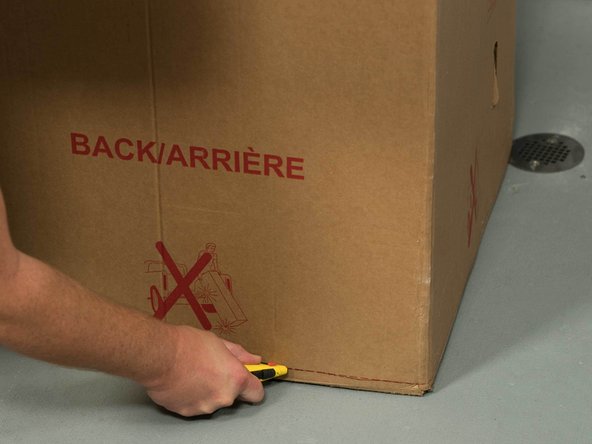
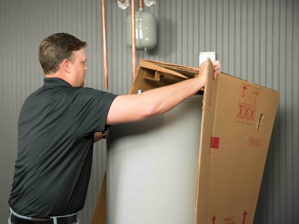
Cut the water heater box along the dotted lines.
-
-
-
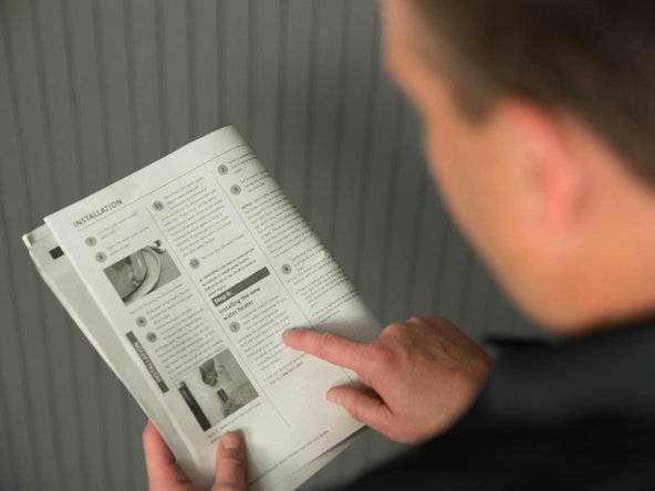
Read the printed installation instructions, including all of the safety warnings, before beginning.
-
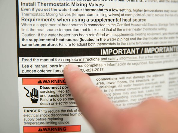
Read all of the labels on the water heater.
-
It is your responsibility to ensure that the installation complies with national, state and local building, plumbing, and electrical codes.
-
Check the water heater’s data plate and ensure that the home’s voltage, wiring size, and circuit breaker are correct for this water heater. Ensure that wire sizes, type, and connections comply with all applicable local codes. In the absence of local codes, follow NFPA-70 and the current edition of the National Electric Code (NEC).
-
NOTICE: If you are not sure you can correctly and safely complete the installation, seek assistance from a qualified person.
-
-
-
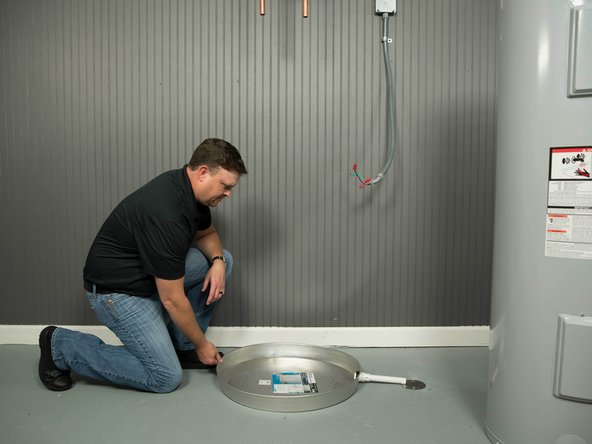
Install a suitable drain pan that is piped to an adequate drain. Install the drain so the water level is limited to a maximum depth of 1-3/4".
-
The drain pan must be at least two inches wider than the diameter of the water heater.
-
-
-
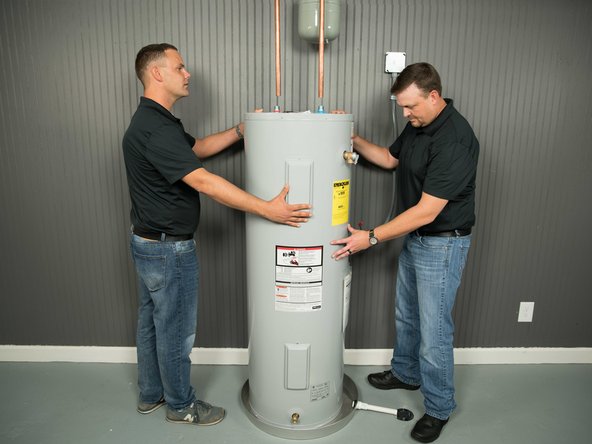
Set the water heater in the drain pan, taking care not to damage the drain pan.
-
CAUTION: Water heaters are heavy. Use two or more people to remove or install a water heater if you don't have an appliance dolly. Failure to do so can result in back or other injury.
-
Verify there is adequate access and space around the water heater for future maintenance.
-
-
-
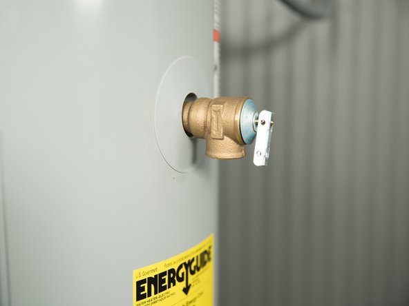
Most Temperature and Pressure (T&P) Relief Valves are installed at the factory. If your T&P Relief Valve is in a separate carton, it must be installed in the opening marked "T&P Relief Valve." Use the new T&P Relief Valve supplied with your new water heater. Do not reuse the old one.
-
WARNING! If your water heater does not have a factory installed T&P Relief Valve, install one (and a discharge pipe) according to the printed installation instructions to avoid serious injury or death from explosion.
-
-
-
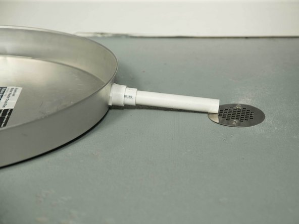
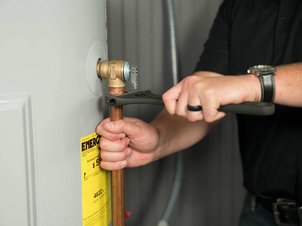
Install the discharge pipe. The discharge pipe should be at least 3/4” inside diameter and sloped for proper drainage. Install it to allow for complete drainage.
-
The discharge pipe must withstand 250°F (121°C) without distortion. Use only copper, PEX, or CPVC pipe. Do not use any other type of pipe, such as PVC, iron, flexible plastic pipe, or any type of hose.
-
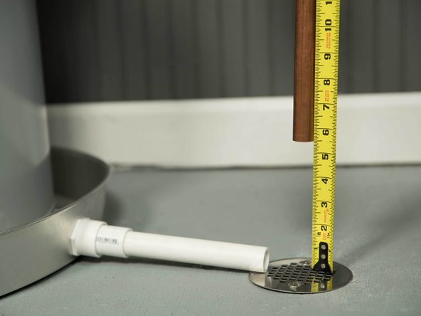
Terminate the discharge pipe at least 1" and a maximum of 6" above a floor drain or outside. Do not drain the discharge pipe into the drain pan; instead, pipe it to an adequate drain.
-
In cold climates, terminate the discharge pipe inside the building to an adequate drain. Outside drains could freeze and obstruct the drain line.
-
WARNING! Do not place any valve or other restriction between the tank and T&P Relief Valve. Do not cap, block, plug, or insert any valve between the T&P Relief Valve and the end of the discharge pipe. Do not install any reducer in the discharge pipe.
-
-
-
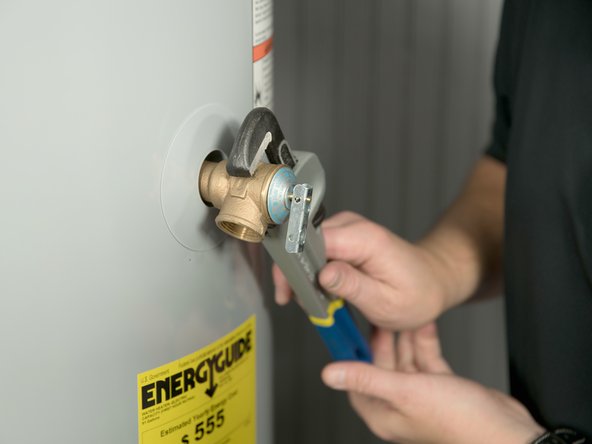
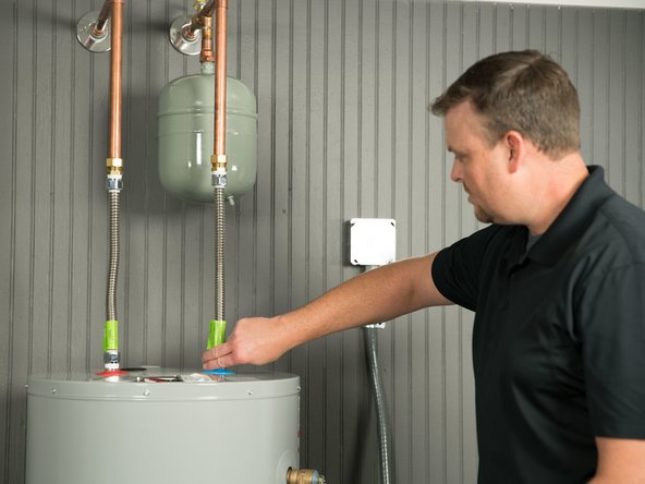
If one is not already installed, install a manual shutoff valve in the cold water line that supplies the water heater. Install the shutoff valve near the water heater so that it is readily accessible. Only use a full-flow ball or gate valve compatible with potable water.
-
This step varies depending on your water heater's location and piping. Consult the installation instructions.
-
-
-
Install a Thermostatic Mixing Valve at each point of use (for example, kitchen sink, bathroom sink, bath, shower) per the valve manufacturer’s instructions.
-
For water heaters that are fed by a solar water heating system (or any other pre-heating system), always install a Thermostatic Mixing Valve or other temperature limiting device in the inlet water supply line to limit water supply inlet temperature to 120°F.
-
WARNING! Hot water can cause severe burns instantly, resulting in severe injury or death. Install Thermostatic Mixing Valves at each point of use to reduce the risk of scalding.
-
-
-
For ease of removing the water heater for service or replacement, use compression fittings to connect the water pipes. If you are soldering copper pipes, use dielectric unions to connect the pipes to the water heater.
-
Installation kits are available with flexible stainless steel connectors and compression fittings that don't require soldering. And many flexible connectors contain built-in dielectric fittings. Use fittings appropriate for the type of pipe in your home. Use copper, PEX or CPVC pipe. Do not use iron or PVC pipe.
-
NOTICE: Do not solder pipes while they are attached to the water heater. The water heater’s inlet and outlet connections contain non-metallic parts which could be damaged.
-
-
-
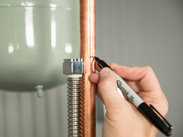
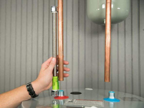
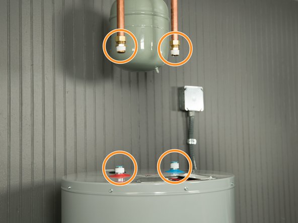
If you are using the installation kit with flexible connectors, measure both of the water lines.
-
-
-
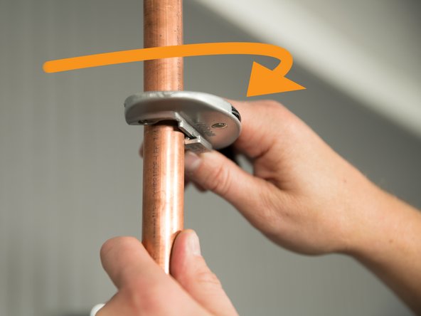
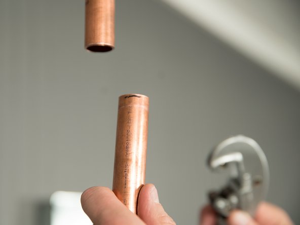
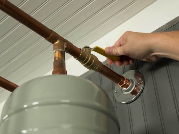
Cut both of the water pipes, but leave them a little longer than the measurement. You can always cut them shorter if necessary.
-
-
-
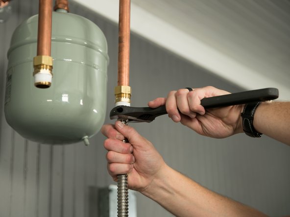
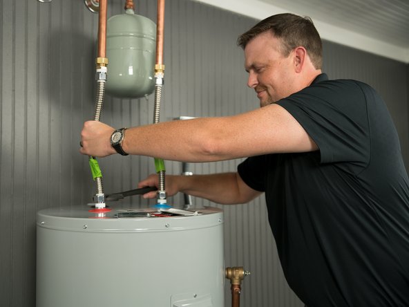
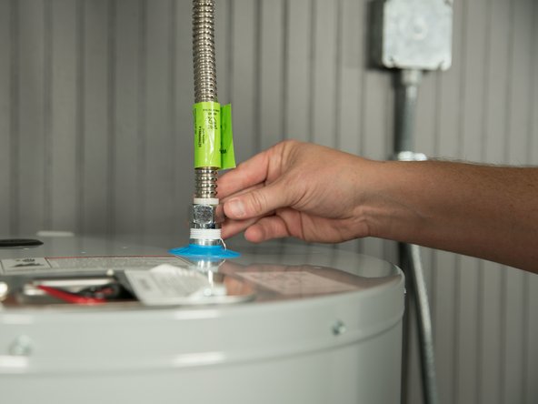
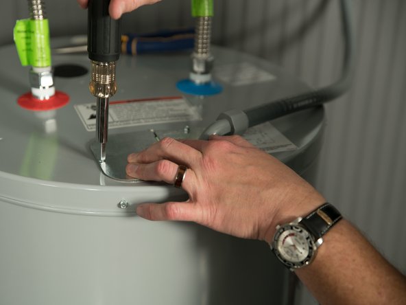
Install compression fittings on both water lines and tighten.
-
Watch this short video to see how that's done.
-
-
-
Use pipe joint compound or plumber's tape on the threaded connections only.
-
-
-
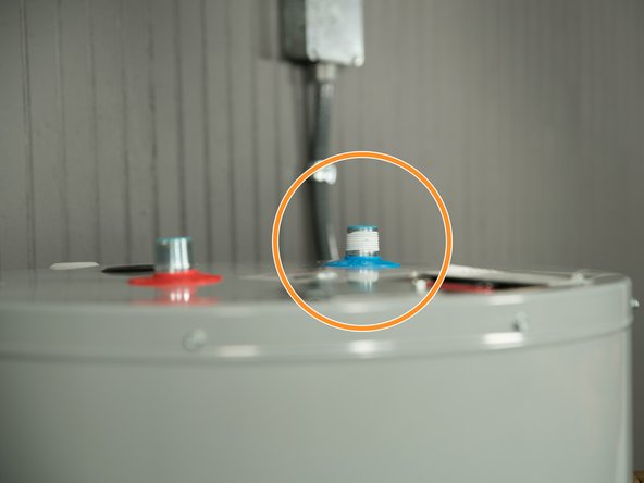
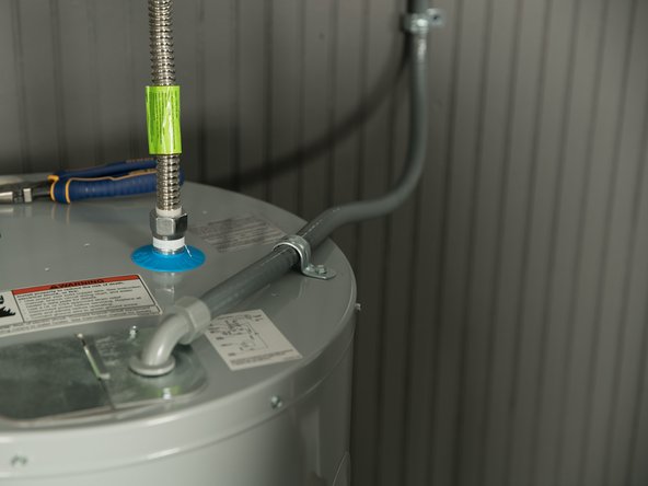
Connect the cold water supply using a 3/4" NPT threaded adapter to the outlet connection on the water heater marked “C” (COLD).
-
Connect the hot water supply using a 3/4" NPT threaded adapter to the outlet connection on the water heater marked “H” (HOT).
-
-
-
Make sure the home's hot and cold water pipes are connected to the correct hot and cold water fittings on the water heater.
-
-
-
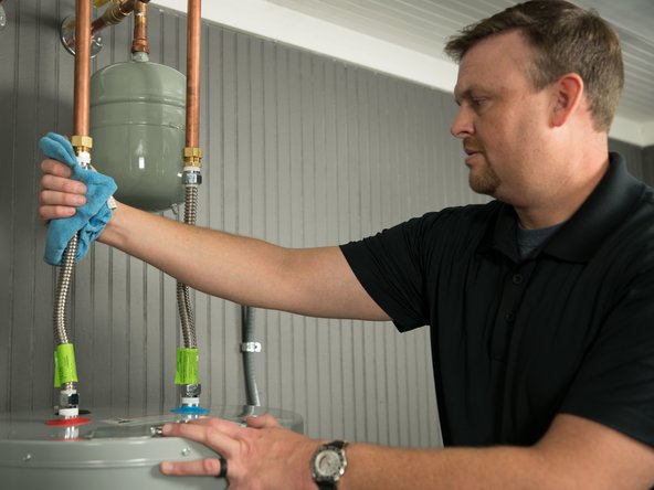
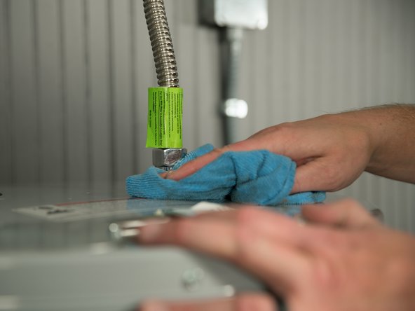
Dry the pipe connections so that any drips or leaks will be apparent.
-
-
-
Turn the cold water supply back ON and fill the tank.
-
-
-
NOTICE: Do not turn electrical power on unless you are sure all of the air is out of the tank and the tank is completely full of water. If power is applied before the tank is completely full of water, the upper element will burn out (dry fire).
-
To remove air from the tank and allow the tank to fill completely with water, follow these steps:
-
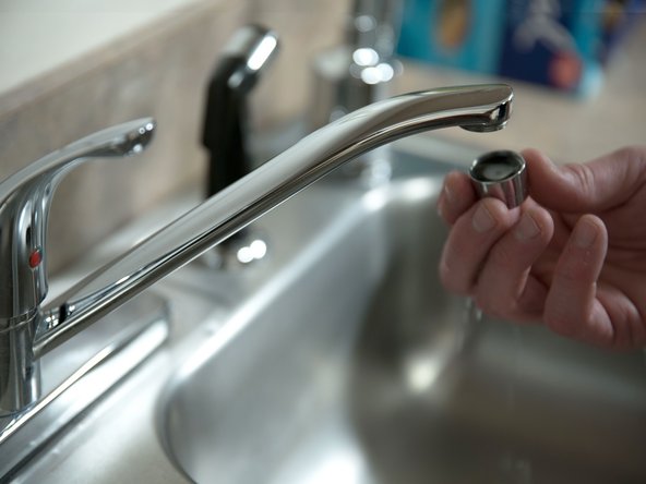
Remove the aerator at the nearest hot water faucet. This allows any debris in plumbing system to be washed out of the pipes.
-
-
-
Open a hot water faucet and allow the water to run until it flows full stream.
-
Let the water run full stream for THREE MINUTES to get all of the air out of the tank.
-
NOTICE: You must remove all the air from the tank and allow the tank to fill completely with water before connecting electrical power.
-
-
-
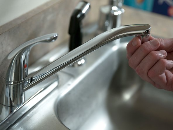
After all of the air has been removed from the tank, close the hot water faucet and replace the aerator.
-
-
-
Check inlet and outlet connections and water pipes for leaks. Tighten fittings or repair any leaks.
-
Almost all leaks occur at connections and are not a tank leak.
-
-
-
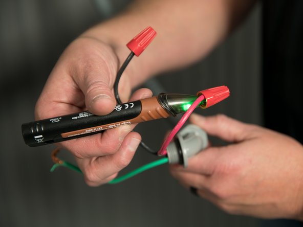
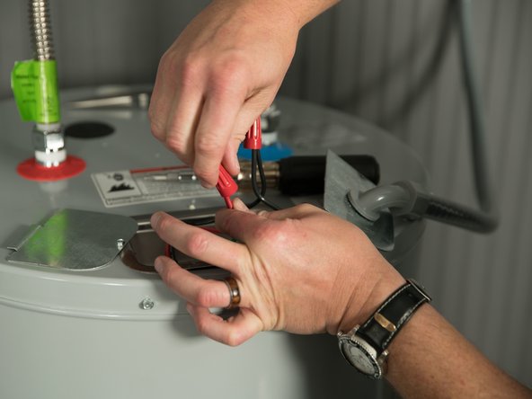
Using a non-contact circuit tester, check the power wires to make certain the power is off.
-
WARNING! Working on an energized circuit can result in severe injury or death from electrical shock. Check wires with a volt meter or circuit tester to make sure power is off.
-
-
-
Install wiring in an approved conduit (if required by local codes).
-
-
-
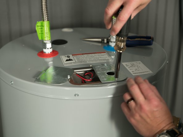
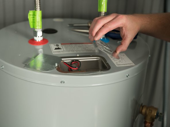
Remove the cover on the electrical junction box on the top of the water heater.
-
-
-
Insert the conduit connector and power wires through the hole in the junction box cover.
-
Attach strain-relief nut.
-
-
-
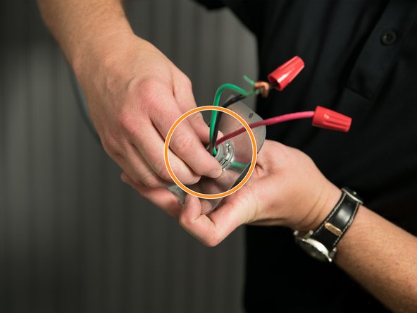
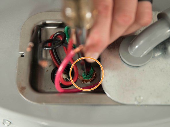
Connect the home's bare copper or green ground wire to the water heater's green ground screw.
-
-
-
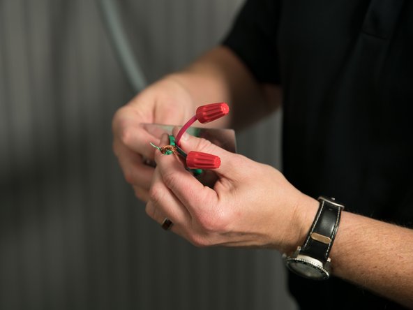
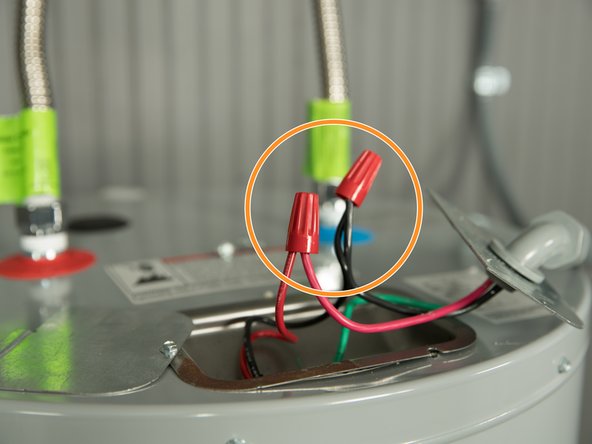
Connect the home’s two power wires to the water heater’s two service wires. Use suitable wire nuts or other approved means to make the power connections.
-
-
-
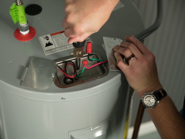
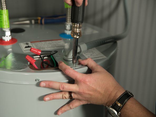
Replace the junction box cover and secure with the screws provided.
-
WARNING! Be sure cover is secured to reduce the risk of fire and electric shock.
-
-
-
Use a UL listed or CSA approved strain relief to secure the electrical wiring to the water heater.
-
-
-
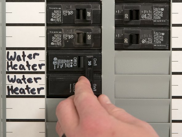
Turn power ON at the circuit breaker (or replace fuses).
-
It may take several hours for a tank of cold water to heat up. If you have no hot water after two hours, refer to the troubleshooting section.
-
-
-
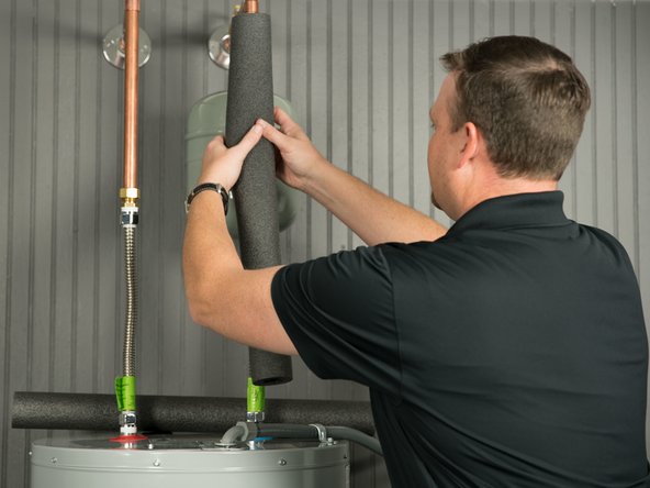
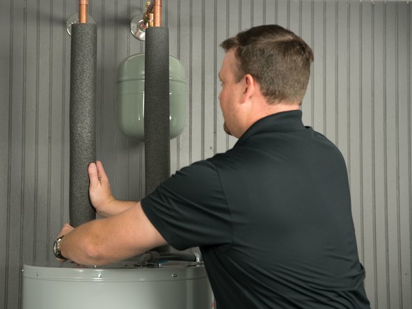
Install insulation (or heat tape) on the water pipes, especially if the indoor installation area is subject to freezing temperatures.
-
Insulating the hot water pipe can increase energy efficiency.
-
-
-
The thermostat(s) on this water heater have been factory set to approximately 120°F to reduce the risk of scald injury. You may wish to set a higher temperature to provide hot water for automatic dishwashers or washing machines, to provide more hot water capacity and to reduce bacterial growth.
-
WARNING! Because of the increased risk from scalding, if you set the water heater’s thermostat(s) higher than 120°F, Thermostatic Mixing Valves at each point of use are recommended to reduce the risk of scalding.
-
Check water temperature at several points of use in your home (for example, bathtub faucet, shower, or lavatory sink) and adjust the Thermostatic Mixing Valves as needed.
-
If you do wish to change the temperature, see Adjusting the Temperature in Standard Electric Troubleshooting.
-


Team
